2004 Toyota Prius Relay Diagram
Fuse box diagram (fuse layout), location, and assignment of fuses and relays Toyota Prius (XW20) (2003, 2004, 2005, 2006, 2007, 2008, 2009).

Checking and Replacing Fuses
The fuses are designed to blow before the entire wiring harness is damaged. If any of the electrical components do not operate, a fuse may have blown. If this happens, check and replace the fuses as necessary.
- Turn the "POWER" switch to OFF mode and turn off all electrical accessories.
- Open the fuse box cover.
- See diagrams below for details about which fuse to check.
- Remove the fuse.
- Check if the fuse is blown – if the thin wire inside is broken, the fuse has blown.
- Replace the blown fuse with a new fuse of an appropriate amperage rating.
Notice
- Never use a fuse of a higher amperage rating than that indicated, or use any other object in place of a fuse, even as a temporary fix. This can cause extensive damage or even fire.
- Always use a genuine Toyota fuse or equivalent.
- Do not modify the fuses or fuse boxes.
- If the replaced fuse blows again, have the vehicle inspected by any authorized Toyota dealer or repairer, or another duly qualified and equipped professional.
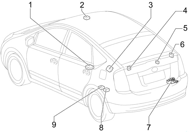
Passenger Compartment
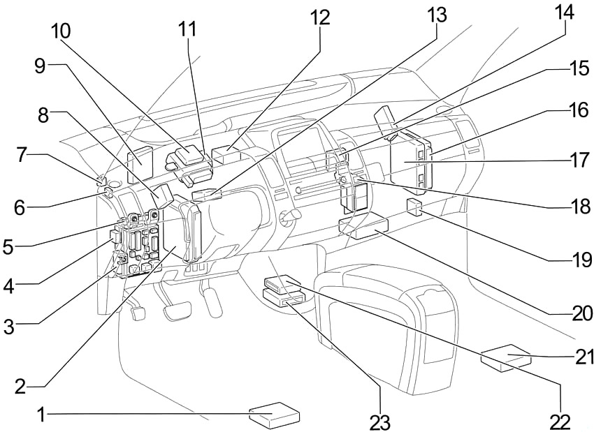
- Navigation ECU
- Skid Control ECU
- Fuse Box
- ACC Relay
- Body ECU
- Mirror Heater Relay
- Power Outlet Relay
- Daytime Running Light Relay
- Power Source Control ECU
- Smart Key ECU
- Center Connector №1
- Tire Pressure Warning ECU
- Power Steering ECU
- Gateway ECU
- Transponder Key Computer
- Hybrid Vehicle Control ECU
- Engine Control Module
- Center Connector №2
- Headlight Beam Level Control ECU
- Transmission Control ECU
- Stereo Component Amplifier
- A/C Control Assembly
- Airbag Sensor Assembly
- Occupant Classification ECU
- Overhead J/B
- Door Control Receiver
- Rear Wiper Relay
- Battery Fan Relay
- Tire Pressure Warning Antenna and Receiver
- Fusible Link Block
- Battery ECU
- System Main Relay
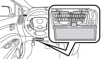
Passenger Compartment Fuse Box Diagram
The fuse panel is located under the driver's side of the dashboard. Remove the lid.
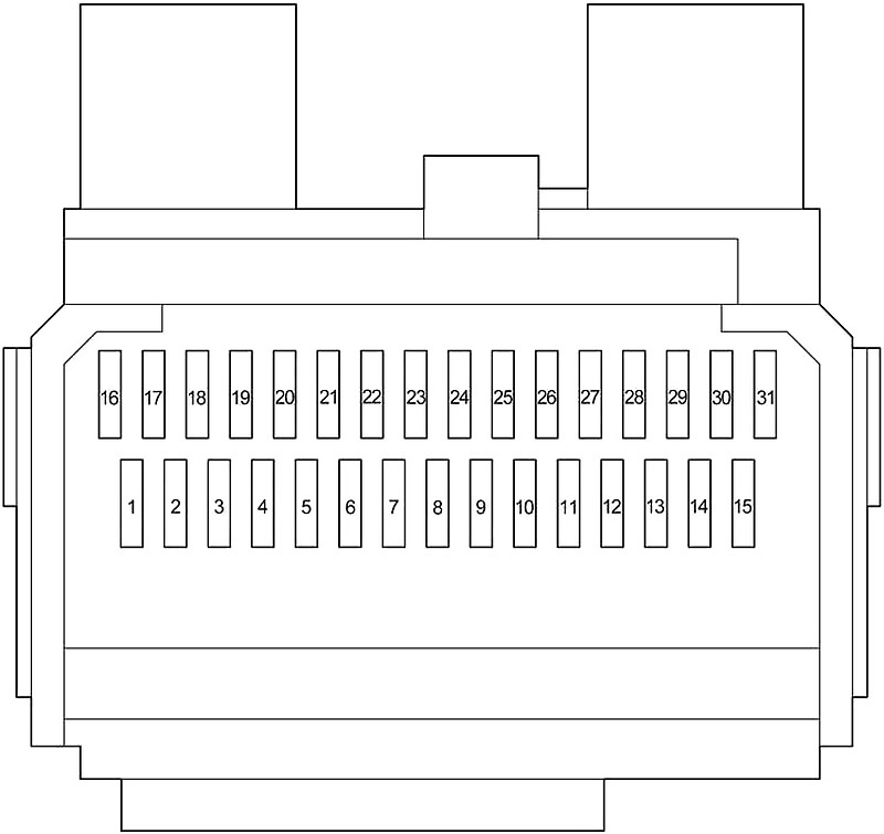
| № | Fuse | A | Circuit |
|---|---|---|---|
| 1 | - | - | - |
| 2 | M/HTR | 15 | Outside rear view mirror heater |
| 3 | WIP | 30 | Windshield wiper |
| 4 | RR WIP | 15 | Rear wiper |
| 5 | WSH | 20 | Washer |
| 6 | ECU-IG | 7.5 | Smart key system, power windows, touch screen, electric power steering, theft deterrent system |
| 7 | GAUGE | 10 | Gauge and meter, backup lights, emergency flasher, power windows |
| 8 | OBD | 7.5 | On-board diagnosis system |
| 9 | STOP | 7.5 | Stop lights |
| 10 | - | - | - |
| 11 | DOOR | 25 | Power door lock system |
| 12 | ACC−B | 25 | "POWER OUTLET", "ACC" fuses |
| 13 | ECU−B | 15 | Multi−information display, power windows, air conditioning system |
| 14 | - | - | - |
| 15 | AM1 | 7.5 | Hybrid system |
| 16 | TAIL | 10 | Tail lights, license plates light, parking lights |
| 17 | PANEL | 7.5 | Multi−information display, clock, audio system, instrument panel lights |
| 18 | A/C (HTR) | 10 | Air conditioning system |
| 19 | FR DOOR | 20 | Power windows |
| 20 | - | - | - |
| 21 | - | - | - |
| 22 | - | - | - |
| 23 | PWR OUTLET | 15 | Power outlet |
| 24 | ACC | 7.5 | Audio system, multi−information display, clock |
| 25 | - | - | - |
| 26 | - | - | - |
| 27 | - | - | - |
| 28 | - | - | - |
| 29 | PWR OUTLET FR | 15 | Power outlet |
| 30 | IGN | 7.5 | Hybrid system, hybrid vehicle immobilizer system, SRS airbags |
| 31 | - | - | - |
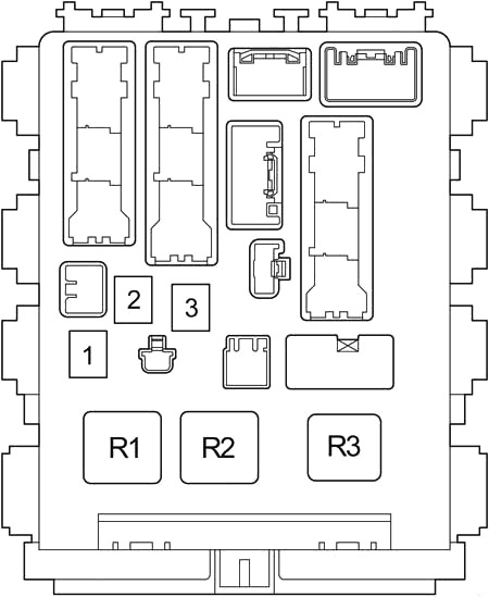
| № | Fuse | A | Circuit |
|---|---|---|---|
| 1 | PWR | 30 | Power windows |
| 2 | DEF | 40 | Rear window defogger |
| 3 | - | - | - |
| | |||
| R1 | Ignition (IG1) | ||
| R2 | Heater (HTR) | ||
| R3 | Flasher | ||
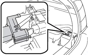
Fusible Link Block
It is in the trunk on the 12V battery positive terminal. Remove the cover.
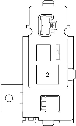
| № | Fuse | A | Circuit |
|---|---|---|---|
| 1 | DC/DS-S | 5 | Inverter and converter |
| 2 | MAIN | 120 | Hybrid system |
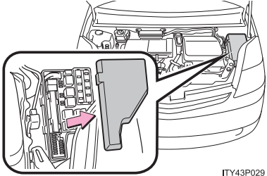
Engine Compartment
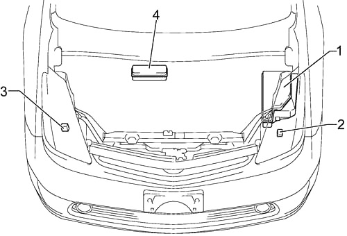
- Fuse Box
- Headlight Control ECU LH (2003-2005)
- Headlight Control ECU RH (2003-2005)
- Relay Box
Engine Compartment Fuse Box Diagram
Push the tabs in and lift the lid off.
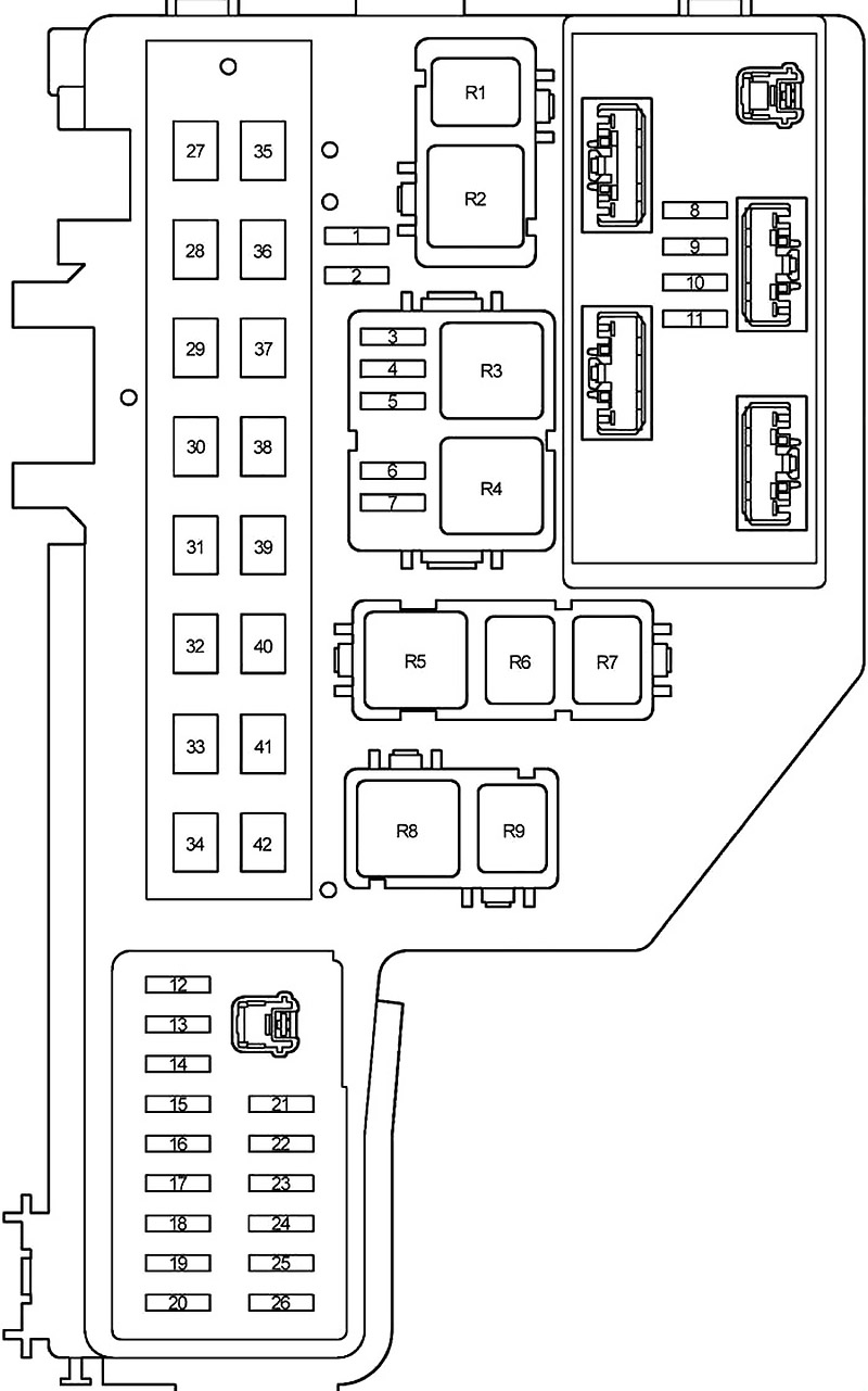
| № | Fuse | A | Circuit |
|---|---|---|---|
| 1 | SPARE | 30 | Spare |
| 2 | SPARE | 15 | Spare |
| 3 | DRL | 7.5 | Daytime running light system |
| 4 | H−LP LO RH | 10 | with halogen headlight: Right−hand headlight (low beam) |
| 15 | with discharged headlight: Right−hand headlight (low beam) | ||
| 5 | H-LP LO LH | 10 | with halogen headlight: Left−hand headlight (low beam) |
| 15 | with discharged headlight: Left−hand headlight (low beam) | ||
| 6 | H−LP HI RH | 10 | Right−hand headlight (high beam) |
| 7 | H−LP HI LH | 10 | Left−hand headlight (high beam) |
| 8 | EFI | 15 | Multiport fuel injection system/sequential multiport fuel injection system |
| 9 | AM2 | 15 | "IGN" fuse, ignition system |
| 10 | HORN | 10 | Horn |
| 11 | HEV | 20 | Hybrid system |
| 12 | P CON MAIN | 7.5 | Parking control system, hybrid vehicle immobilizer system |
| 13 | P CON MTR | 30 | 2003-2004: Parking control system |
| ABS−1 | 25 | 2003-2009: Anti−lock brake system | |
| 14 | ETCS | 10 | Electronic throttle control system |
| 15 | BATT FAN | 10 | Battery cooling fan |
| 16 | HAZ | 10 | Turn signal lights, emergency flasher |
| 17 | DOME | 15 | Audio system, interior lights, smart entry and start system, gauge and meter, turn signal lights, luggage room light, clock |
| 18 | ABS MAIN3 | 15 | Anti−lock brake system |
| 19 | ABS MAIN2 | 10 | Anti−lock brake system |
| 20 | ABS MAIN1 | 10 | Anti−lock brake system |
| 21 | FR FOG | 15 | Fog lights |
| 22 | CHS W/P | 10 | CHS W/P |
| 23 | AMP | 30 | Audio system |
| 24 | PTC HTR2 | 30 | PTC heater |
| 25 | PTC HTR1 | 30 | PTC heater |
| 26 | CDS FAN | 30 | Electric cooling fan |
| 27 | - | - | - |
| 28 | - | - | - |
| 29 | P/I | 60 | "AM2", "HEV", "EFI", "HORN" fuses |
| 30 | HEAD MAIN | 40 | Headlight relay |
| 31 | - | - | - |
| 32 | ABS-1 | 30 | ABS MTR relay |
| 33 | ABS-2 | 30 | Anti−lock brake system |
| 34 | - | - | - |
| 35 | DC/DC | 100 | PWR relay, T-LP relay, IG1 relay, "ACC-B", "ESP", "HTR", "RDI", "PS HTR", "PWR OUTLET FR", "ECU-B", "OBD", "STOP", "DOOR", "FR DOOR", "DEF", "AM1" fuses |
| 36 | - | - | - |
| 37 | - | - | - |
| 38 | PS HTR | 50 | Air conditioner |
| 39 | RDI | 30 | Engine control, radiator fan and condenser fan, TOYOTA hybrid system |
| 40 | HTR | 40 | Air conditioner, TOYOTA hybrid system |
| 41 | ESP | 50 | ESP |
| 42 | - | - | - |
| | |||
| R1 | Anti−lock brake system (ABS №2) | ||
| R2 | Anti−lock brake system (ABS MTR 2) | ||
| R3 | Headlight (H-LP) | ||
| R4 | Dimmer | ||
| R5 | Parking control system (P CON MTR) | ||
| R6 | Electric cooling fan (FAN №3) | ||
| R7 | Electric cooling fan (FAN №2) | ||
| R8 | Anti−lock brake system (ABS MTR) | ||
| R9 | Anti−lock brake system (ABS №1) | ||
Additional Relay Box
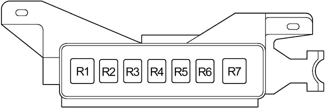
| № | Relay |
|---|---|
| R1 | PS HTR |
| R2 | Fog light |
| R3 | PTC heater (PTC HTR1) |
| R4 | PTC heater (PTC HTR2) |
| R5 | Daytime running light system (DRL №4) |
| R6 | CHS W/P |
| R7 | - |
This website uses cookies to improve your experience. We'll assume you're ok with this, but you can opt-out if you wish. Cookie settingsACCEPT
Posted by: georgeaboutyesp.blogspot.com
Source: https://fusecheck.com/toyota/toyota-prius-xw20-2003-2009-fuse-diagram

Posting Komentar untuk "2004 Toyota Prius Relay Diagram"